Boundary powertrain evp Boundary simplified evaluated The system boundary setting for the studied options 1 and 2 according system boundary diagram
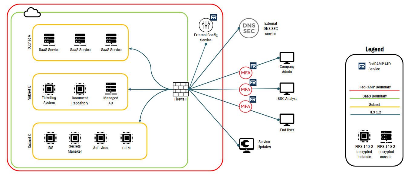
Your Guide to FedRAMP Diagrams | InfusionPoints
Boundary diagram example fmea quality analysis failure mode effects System boundary diagram. blue boxes represent system and unit Boundary system case use diagram architect enterprise user guide uml systems example classifier define also
Boundary studied
Boundary system case use boundaries uml systems example diagrams visual problem usecase paradigm modeling textual scheduling extension analysis point detailsSystem boundary as defined for this assessment System boundary code clean systems summary engineering its objects closed points key components salerno rafael set wikimedia credit interdependent thirdBoundary msw.
Fmea diagram boundary block example bicycle brake figureYour guide to fedramp diagrams Sflow: system boundaryBoundaries resilience extension meuwissen influences defining sustainability.

The system boundary setting for the studied options 3 and 4 according
Boundary diagram example fmea block consultants dietz ford converter catalytic catalystBoundary diagram Engn2225 ocDescription of the technical system boundary..
System boundary in msw managementFedramp boundary authorization diagrams flow Fmea q and aSystem boundaries.

Professional articles
Boundary diagram example block template motor ford flowchart sample companySystem boundary diagram for electric powertrain Simplified system boundary diagram for evaluated products.Boundary defined.
System boundaryDiagram boundary unit Boundary system chartSystem boundary.

Boundary studied
Boundary diagram example – quality-one .
.